Installing rubber tracks on an excavator requires adherence to manufacturer specifications and an understanding of the machine’s undercarriage architecture. Executing this task properly ensures the operational integrity of the excavator and reduces the risk of downtime due to track failure. Below is a comprehensive guideline tailored to meet professional standards in track installation.
Initial Considerations:
Ensuring the work area is unobstructed and level is of utmost importance. Gather all necessary tooling and verify that the replacement tracks to be installed are appropriate for the excavator’s model specifications.
Ensuring the work area is unobstructed and level is of utmost importance. Gather all necessary tooling and verify that the replacement tracks to be installed are appropriate for the excavator’s model specifications.
Step 1: Secure the Work Area
Identify a level and firm area to elevate the excavator. Lower all attachments to the ground to provide additional stability, and ensure the machine is powered down with the parking brake engaged.
Identify a level and firm area to elevate the excavator. Lower all attachments to the ground to provide additional stability, and ensure the machine is powered down with the parking brake engaged.
Step 2: Elevate the Side
Using a hydraulic jack, elevate the side of the excavator that you’ll work on first. Place industrial-grade jack stands under the frame to maintain a steady elevation. The undercarriage should be adequately accessible without any points of contact with the ground.
Using a hydraulic jack, elevate the side of the excavator that you’ll work on first. Place industrial-grade jack stands under the frame to maintain a steady elevation. The undercarriage should be adequately accessible without any points of contact with the ground.
Step 3: Release Track Tension
Locate the track-adjusting valve and remove the grease valve or fitting to release tension on the track. This will allow the idler to retract and the track to loosen, facilitating removal.
Locate the track-adjusting valve and remove the grease valve or fitting to release tension on the track. This will allow the idler to retract and the track to loosen, facilitating removal.
Step 4: Detach the Current Track
Maneuver around the track’s weight and bulk prudently as you disengage it from the sprocket and guide rollers. Remove it from the undercarriage by peeling off around the sprocket.
Maneuver around the track’s weight and bulk prudently as you disengage it from the sprocket and guide rollers. Remove it from the undercarriage by peeling off around the sprocket.
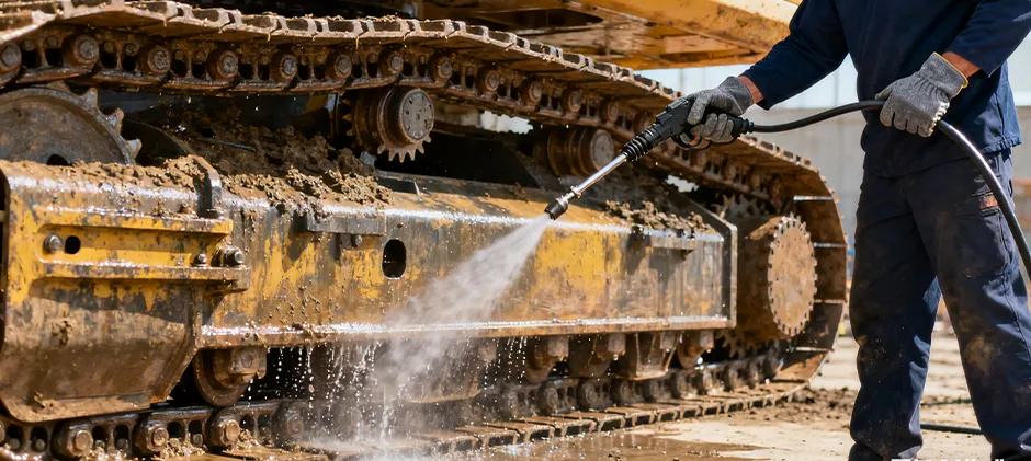
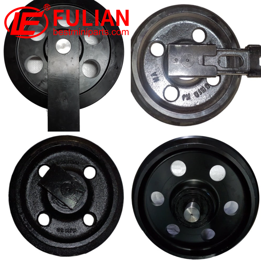
Step 5: Undercarriage Inspection
Conduct a meticulous inspection of the sprockets, idlers, and rollers. Check for excessive wear, damage, or misalignment. This is the optimal juncture to perform any corrective maintenance to these components.
Conduct a meticulous inspection of the sprockets, idlers, and rollers. Check for excessive wear, damage, or misalignment. This is the optimal juncture to perform any corrective maintenance to these components.
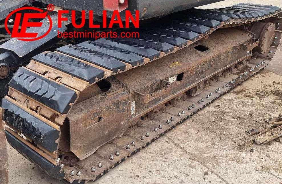
Step 6: Position the New Track
Position the new track alongside the undercarriage. Begin the installation process from the sprocket-end by aligning the track correctly, ensuring it sits uniformly along the track frame.
Position the new track alongside the undercarriage. Begin the installation process from the sprocket-end by aligning the track correctly, ensuring it sits uniformly along the track frame.
Step 7: Install the Track
Gradually rotate the sprocket, guiding the track onto its teeth, and guide across the top rollers. Articulate the idler wheel by advancement of the track around the undercarriage, attending to any pinch points or misalignments as the track seats into place.
Gradually rotate the sprocket, guiding the track onto its teeth, and guide across the top rollers. Articulate the idler wheel by advancement of the track around the undercarriage, attending to any pinch points or misalignments as the track seats into place.
Step 8: Tension the Track
Reinsert the grease valve and use a calibrated grease gun to inject grease into the tensioner. This will propagate the idler forward, augmenting tension on the track. Cease when proper tension is attained, which is generally indicated by the manufacturer’s tension specification, usually found in the service manual.
Reinsert the grease valve and use a calibrated grease gun to inject grease into the tensioner. This will propagate the idler forward, augmenting tension on the track. Cease when proper tension is attained, which is generally indicated by the manufacturer’s tension specification, usually found in the service manual.
Step 9: Lower the Excavator
Once the track is tensioned accurately, gently lower the excavator, ensuring the supports are fully removed.
Once the track is tensioned accurately, gently lower the excavator, ensuring the supports are fully removed.
Step 10: Validation Check
Power the machine and rotate the tracks slowly to ensure no binding or misalignment occurs. Verify that the excavator exhibits stable, unimpeded track mobility before full operational deployment.
Power the machine and rotate the tracks slowly to ensure no binding or misalignment occurs. Verify that the excavator exhibits stable, unimpeded track mobility before full operational deployment.
Bear in mind that the keystone of this procedure is conforming to the exacting criteria set forth by the excavator manufacturer. Deviations may lead to compromised functionality or preclude warranty coverages. Professional technicians will always follow best practices in line with OEM (Original Equipment Manufacturer) guidelines, ensuring extended durability and reliability of the excavator tracks. Should uncertainties arise during the track replacement process, consulting with the OEM or a seasoned technician is recommended to prevent inadvertent machine damage or personal injury.
Fulian Operation Team
2024.3.5